IST – Products
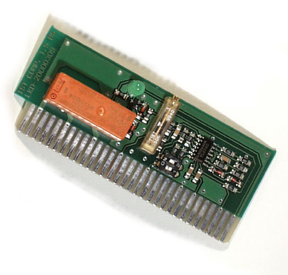
Comparator
The comparator can be plugged into any of the seven slots. Depending on the slot, the comparator is thus assigned to different terminal groups on the setpoint controller rack.
The comparator module functions as follows:
The voltage value applied to the input (terminal 11) is always compared with the switch value set on the potentiometer (P1). This switch value can take the following forms: positive, negative, or a value for positive and negative input signals. A switching hysteresis (approx. 200 mV) prevents unwanted oscillation by the comparator around the set switching threshold.
The operating mode can be selected by means of the switches S1 and S2. The operating state of the output relay then changes when the input voltage either exceeds or drops below the switching threshold, according to the selected setting (mode). An LED on the module displays the status of the relay. The changeover contact of this relay is available as an output.
Positive threshold (see Figure 2.1)
If the input signal becomes more positive than the switching threshold set for positive, the relay drops out and the output switches.
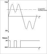
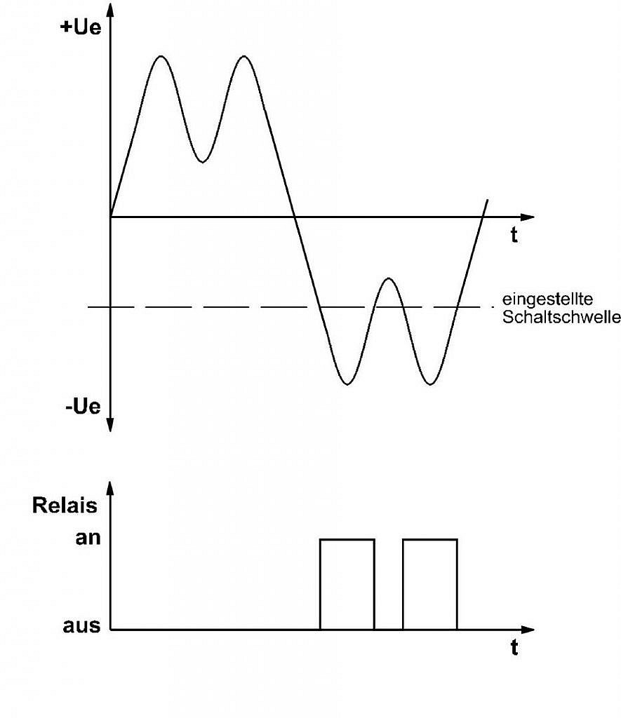
Negative threshold (see Figure 2.2)
If the input signal becomes more positive than the switching threshold set for positive, the relay drops out and the output switches.
Detailed instructions on settings can be found in the instruction manual.